


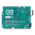


Arduino Uno R3 USB Microcontroller
$27.60
Description
- Arduino Uno R3 USB Microcontroller
- Arduino microcontroller module with USB connection
- Wide variety of accessory “Shields” available
- It is intended for roboticists, artists, designers and hobbyists
- Variety of I/O pins including analog, digital, PWM and more
- Based on the ATmega328 (removable DIP IC)
- Revision 3
The Arduino Uno is a microcontroller board based on the ATmega328 microchip. It has 14 digital input/output pins (of which 6 can be used as PWM outputs), 6 analog inputs, a 16 MHz crystal oscillator, a USB connection, a power jack, an ICSP header, and a reset button. It contains everything needed to support the microcontroller; simply connect it to a computer with a
The Arduino Uno differs from all preceding boards in that it does not use the FTDI USB-to-serial driver chip. Instead, it features the Atmega16U2 programmed as a USB-to-serial converter. “Uno” means one in Italian and is named to mark the upcoming release of Arduino 1.0. The Uno and version 1.0 will be the reference versions of Arduino, moving forward. The Uno is the latest in a series of USB Arduino boards, and the reference model for the Arduino platform.

The Arduino Uno can be powered via the USB connection or with an external power supply. The power source is selected automatically. External (non-USB) power can come either from an AC-to-DC adapter (wall-wart) or battery. The adapter can be connected by plugging a 2.1 mm center-positive plug into the board’s power jack. Leads from a battery can be inserted in the Gnd and Vin pin headers of the POWER connector. The board can operate on an external supply of 6 to 20 volts.
The Arduino Uno can be programmed with the Arduino software. Select “Arduino Uno from the Tools > Board menu (according to the microcontroller on your board). For details, see the reference and tutorials. The ATmega328 on the Arduino Uno comes preburned with a bootloader that allows you to upload new code to it without the use of an external hardware programmer.

Power
The Arduino Uno can be powered via the USB connection or with an external power supply. The power source is selected automatically.
External (non-USB) power can come either from an AC-to-DC adapter (wall-wart) or battery. The adapter can be connected by plugging a 2.1 mm center-positive plug into the board’s power jack. Leads from a battery can be inserted in the Gnd and Vin pin headers of the POWER connector.
The board can operate on an external supply of 6 to 20 volts. If supplied with less than 7V, however, the 5V pin may supply less than five volts and the board may be unstable. If using more than 12 V, the voltage regulator may overheat and damage the board. The recommended range is 7 to 12 volts.
The power pins are as follows:
- VIN. The input voltage to the Arduino board when it’s using an external power source (as opposed to 5 volts from the USB connection or other regulated power source). You can supply voltage through this pin, or, if supplying voltage via the power jack, access it through this pin.
- 5 V. This pin outputs a regulated 5 V from the regulator on the board. The board can be supplied with power either from the DC power jack (7 – 12 V), the USB connector (5 V), or the VIN pin of the board (7-12 V). Supplying voltage via the 5 V or 3.3 V pins bypasses the regulator, and can damage your board. We don’t advise it.
- 3V3. A 3.3 volt supply generated by the on-board regulator. Maximum current draw is 50 mA.
- GND. Ground pins.
- IOREF. This pin on the Arduino board provides the voltage reference with which the microcontroller operates. A properly configured shield can read the IOREF pin voltage and select the appropriate power source or enable voltage translators on the outputs for working with the 5 V or 3.3 V.

Memory
The ATmega328 has 32 KB (with 0.5 KB used for the bootloader). It also has 2 KB of SRAM and 1 KB of EEPROM (which can be read and written with the EEPROM library).
- Arduino Uno R3 USB Microcontroller
- Length: 2.7 inches
- Width: 2.1 inches
The USB connector and power jack extend beyond these dimensions.
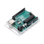
Four screw holes allow the board to be attached to a surface or case.
Note that the distance between digital pins 7 and 8 is 160 mil (0.16″), not an even multiple of the 100 mil spacing of the other pins.
PDF Files
ZIP File
Website
- RobotShop Learning Center: Arduino 5 Minute Tutorials
- Arduino Language Reference and Website
Making Robots With The Arduino, Part 1, by Gordon McComb, Servo Magazine November 2010
- Microcontroller: ATmega328
- Operating Voltage: 5 V
- Input Voltage (recommended): 7-12 V
- Input Voltage (limits): 6-20 V
- Digital I/O Pins: 14 (of which 6 provide PWM output)
- Analog Input Pins: 6
- DC Current per I/O Pin: 40 mA
- DC Current for 3.3V Pin: 50 mA
- Flash Memory: 32 KB (ATmega328) of which 0.5 KB used by bootloader
- SRAM: 2 KB (ATmega328)
- EEPROM: 1 KB (ATmega328)
- Clock Speed: 16 MHz


MAECENAS IACULIS
Vestibulum curae torquent diam diam commodo parturient penatibus nunc dui adipiscing convallis bulum parturient suspendisse parturient a.Parturient in parturient scelerisque nibh lectus quam a natoque adipiscing a vestibulum hendrerit et pharetra fames nunc natoque dui.
ADIPISCING CONVALLIS BULUM
- Vestibulum penatibus nunc dui adipiscing convallis bulum parturient suspendisse.
- Abitur parturient praesent lectus quam a natoque adipiscing a vestibulum hendre.
- Diam parturient dictumst parturient scelerisque nibh lectus.
Scelerisque adipiscing bibendum sem vestibulum et in a a a purus lectus faucibus lobortis tincidunt purus lectus nisl class eros.Condimentum a et ullamcorper dictumst mus et tristique elementum nam inceptos hac parturient scelerisque vestibulum amet elit ut volutpat.


Reviews
There are no reviews yet.